
Permanent Formwork Magnet selection is a practical engineering decision, not a catalogue exercise. Magnet type affects panel positioning, holding force, release, and the time crews spend correcting movement on a casting bed. A compact box magnet, a push-pull unit, and a custom magnetic assembly serve different formwork details. The right choice depends on the mould surface, concrete pressure, reinforcement layout, and site handling.
The scale of the productivity challenge is documented. McKinsey Global Institute’s 2017 report, Reinventing Construction: A Route to Higher Productivity, found that construction labour productivity grew about 1% annually over two decades, compared with 2.8% for the global economy. That report does not measure magnet performance. It does, however, underline why small, repeatable improvements in setup and alignment deserve attention. A magnet that slips, binds, or takes extra effort to release can erase those gains.
This guide compares the leading Permanent Formwork Magnet types in 2026, focusing on their design, typical applications, and selection trade-offs. It also considers practical checks, such as contact-surface cleanliness and reliable switching. One source limitation matters: no article or independently verifiable quotation from a named Permanent Formwork Magnet specialist was provided. I will not invent an expert’s words. That gap deserves scrutiny; product claims should be checked against test data and manufacturer documentation before a system is specified.
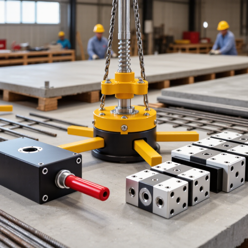
Permanent formwork magnets usually combine a permanent magnet block, a steel housing, pole shoes, and a release mechanism. Some units also include an adapter plate or threaded points for connecting different formwork profiles. The housing protects the magnetic assembly and helps direct its field toward the steel casting bed. Air gaps matter. Rust, concrete residue, or a bent contact face can reduce the effective holding force.
When activated, the mechanism directs magnetic flux through the pole shoes and into the steel bed. The resulting attraction holds the formwork in position without drilling or welding. A lever or push-button system can shift the magnetic circuit for release, depending on the design. Operators should confirm that the bed is compatible and consult the unit’s rated capacity; holding force varies with surface condition and material thickness. In practice, a clean diagram can make the setup look simpler than it is. Casting beds are not always perfectly flat, and even a small patch of debris may change contact. A quick visual check is useful, though it cannot replace the specified inspection and handling procedure.
Box magnets help crews secure side forms to a steel casting bed without drilling or clamping each section. Their compact steel housings contain permanent magnets, while a release button or lever helps switch the magnetic hold on and off. Place each unit flat against the bed, then check that the form sits square. Fast, but not careless.
A clean contact surface matters. A thin layer of concrete residue or a small metal chip can leave a gap and weaken the hold. In daily production, this is easy to miss when teams are moving quickly. Brush the bed, position the magnet, and confirm the form does not shift under hand pressure. For tall forms or heavy concrete sections, select holding force based on expected pressure, vibration, and the form layout—not speed alone.
Box magnets can shorten setup time on repeated pours because crews can reposition them as dimensions change. Release mechanisms also make stripping more controlled after the concrete has gained sufficient strength. Avoid striking the housing or forcing a stuck unit with a long pry bar; damaged parts may not hold consistently next time. A simple inspection for worn buttons, cracks, and packed debris is useful, though it can feel like one more task at the end of a shift.
Button Magnets for Recessed and Embedded Formwork
Button magnets are compact fixtures used to hold inserts or create recesses in steel formwork. Their round profile suits small openings, such as shallow pockets for lifting anchors or connection points. A flat contact face helps keep the magnet seated against the form surface. The concrete then forms around the insert while the magnet helps maintain its position. Small details matter. A thin gap, rust, or concrete residue can reduce magnetic grip, so clean contact surfaces before each pour.
For embedded components, choose a button magnet sized for the insert and expected placement forces. Check the formwork steel thickness and magnet’s holding capacity; vibration and movement during pouring can shift poorly secured parts. Keep the insert aligned, and verify that the magnet releases without damaging the recess after curing. A practical mock-up can reveal problems with fit and removal. Not every job needs a button magnet. Larger recesses or unusual shapes may call for another fixture, and relying on nominal holding force alone is risky. Test the actual setup.
| Button Magnet Configuration | Typical Formwork Connection | Suitable Uses | Main Advantages | Selection and Use Considerations |
|---|---|---|---|---|
| Threaded-stud button magnet | A projecting threaded stud connects to a compatible recess former, insert, or fixture. | Positioning recessed formers and embedded components where a matching threaded connection is specified. | Provides a direct, compact connection and can be removed and reused when the assembly is designed for reuse. | Check thread size, engagement, alignment, and the intended concrete-side geometry. Do not assume that different thread standards are interchangeable. |
| Internal-thread button magnet | A threaded hole in the magnet accepts a matching bolt or threaded accessory. | Fixing accessories or formwork components that use a compatible screw connection. | Allows the fastener length or accessory to be selected for the assembly and can provide a low-profile connection. | Use the specified fastener and tightening method. Keep concrete, debris, and damaged threads from interfering with full engagement. |
| Through-hole or countersunk button magnet | A bolt passes through the magnet; a countersunk version can seat a compatible countersunk-head screw. | Mechanical attachment to a plate, bracket, or formwork accessory where through-fixing is required. | Offers a straightforward bolted interface and can help keep the fixing close to the mounting surface. | Match the hole and screw geometry. A countersunk screw should seat correctly; incorrect seating can affect contact and assembly fit. |
| Flat-face button magnet | The flat magnetic face sits against a suitable ferromagnetic formwork surface; a separate connection may attach the component. | Temporary positioning on steel formwork during setup of recessed or embedded features. | Simple to place, remove, and reposition when access is available and the mating surfaces are clean. | Holding performance depends on the contact surface, air gaps, coatings, alignment, and loading direction. Concrete residue or a rough surface can reduce contact. |
| Button magnet with a custom adapter | A purpose-designed adapter links the magnet to a specific recess former or embedded-part geometry. | Assemblies with non-standard shapes, clearances, or positioning requirements. | Can provide a tailored fit while keeping the magnetic base reusable across compatible setups. | Confirm adapter strength, fit, and cleanability as part of the full assembly. Validate the configuration before production use. |
Selection note: Button magnets are permanent-magnet fixtures, not lifting devices. Choose a configuration using the formwork and component specifications, and verify holding performance under actual contact and loading conditions; rated pull values can differ from performance in service.
Permanent-formwork systems for modular moulds usually rely on two magnet formats: side-forming units and magnetic rails. Side-forming magnets clamp steel shutters to a casting bed, keeping edges aligned during concrete placement and vibration. Compact box-style units suit short, repositioned panels; longer rails distribute holding force along continuous or repeated mould lines. Some rail systems accept movable stops, helping crews change panel widths without drilling new fixing points. The choice depends on shutter height, concrete pressure, vibration, bed flatness, and lifting access—not magnet force alone.
McKinsey Global Institute reported construction productivity growth of about 1% annually over two decades, compared with 2.8% for the global economy (Reinventing Construction, 2017). That supports repeatable factory setups, but does not prove magnets alone improve output. A practical check: wipe the bed, seat each unit fully, then test the assembly before pouring. Even a thin grout film or coating can create a gap and reduce holding force. Small gaps matter. Specify pull-off and shear capacity for the actual mould load, then verify spacing under vibration. Catalogue ratings rarely describe a worn, dusty production bed. Track release time, alignment drift, and cleaning needs across several cycles; these details may reveal a better rail layout.
Matching permanent formwork magnets to the job starts with the contact surface. Box magnets provide strong, concentrated holding force on steel casting tables and suit repeated panel layouts. Button magnets are smaller and useful where fixing points are limited. Magnetic rails spread support along long, straight edges, helping keep narrow formwork sections aligned. The right type depends on panel size, concrete pressure, and the spacing of attachment points.
Steel formwork usually accepts magnets directly, provided the surface is clean and flat. Aluminum, timber, and plywood are non-magnetic, so they need a compatible steel plate or receiver; check that the connection transfers the expected load. For irregular panels or frequent repositioning, compact magnets can be easier to place, but they may offer less holding area. Test a sample setup under realistic vibration and loading. A catalog rating alone is not enough.
Tips: Remove concrete residue before installation, then check each magnet for movement after vibration. Keep a small gap? Don’t. Even a thin layer of debris can reduce contact and holding force. Record the panel material, magnet spacing, and release method that worked on site; those notes can prevent repeat adjustments, though every project still needs its own verification.